
Q25LTR-GN/WB
ILLUMINATED PUSH-BUTTON
Trade Price
£20.95
Per
1
Unit
EACH
Pack Quantity
1


Information
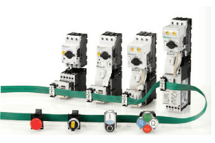
Eaton Moeller® series RMQ16 Illuminated pushbutton actuator, green, maintained, +filament lamp 24V Q25LTR-GN/WB
Technical Specifications
Product Length/Depth
59 mm
Product Height
25 mm
Product Width
25 mm
Product Weight
0.011 kg
Certifications
IEC/EN 60947-5
CSA Class No.: 3211-03
IEC/EN 60947
CSA
UL 508
CSA File No.: 46552
CSA-C22.2 No. 14-05
UL Category Control No.: NKCR
UL File No.: E29184
UL
CE
Bezel color
Black
Bezel material
Plastic
Design
Flat
Fitted with:
Filament bulb (24 V)
Inscription
Blank
Degree of protection
IP65
NEMA 1
Degree of protection (front side)
IP65
NEMA 1
Lifespan, mechanical
30,000,000 Operations
Opening diameter
16 mm
Operating frequency
1800 Operations/h
Overvoltage category
III
Pollution degree
3
Product category
RMQ16
Rated impulse withstand voltage (Uimp)
800 V AC
Size
Front dimensions: 25 x 25 mm
Suitable for
Illumination
Terminal capacity
0.5 - 1.0 mm²
Terminal size
2.8 x 0.8 mm to DIN 46244, Blade terminal
2.8 x 0.8 mm to DIN 46247 and IEC 60760, Fast-on connectors
Type
Illuminated pushbutton actuator
Mounting position
As required
Shock resistance
Mechanical, According to IEC/EN 60068-2-27
40 g, Mechanical, According to IEC/EN 60068-2-27, Sinusoidal shock 11 ms
Ambient operating temperature - min
-25 °C
Ambient operating temperature - max
60 °C
Ambient operating temperature (enclosed) - min
25 °C
Ambient operating temperature (enclosed) - max
40 °C
Climatic proofing
Damp heat, constant, to IEC 60068-2-78
Damp heat, cyclic, to IEC 60068-2-30
Rated insulation voltage (Ui)
250 V
Rated operational voltage (Ue) at AC - max
24 V
Actuating force
4 N
Actuator color
Green
Actuator function
Switching function latching
Maintained
Connection to SmartWire-DT
No
Equipment heat dissipation, current-dependent Pvid
0 W
Heat dissipation capacity Pdiss
0 W
Heat dissipation per pole, current-dependent Pvid
0 W
Rated operational current for specified heat dissipation (In)
0 A
Static heat dissipation, non-current-dependent Pvs
1 W
10.2.2 Corrosion resistance
Meets the product standard's requirements.
10.2.3.1 Verification of thermal stability of enclosures
Meets the product standard's requirements.
10.2.3.2 Verification of resistance of insulating materials to normal heat
Meets the product standard's requirements.
10.2.3.3 Resist. of insul. mat. to abnormal heat/fire by internal elect. effects
Meets the product standard's requirements.
10.2.4 Resistance to ultra-violet (UV) radiation
Please enquire
10.2.5 Lifting
Does not apply, since the entire switchgear needs to be evaluated.
10.2.6 Mechanical impact
Does not apply, since the entire switchgear needs to be evaluated.
10.2.7 Inscriptions
Meets the product standard's requirements.
10.3 Degree of protection of assemblies
Does not apply, since the entire switchgear needs to be evaluated.
10.4 Clearances and creepage distances
Meets the product standard's requirements.
10.5 Protection against electric shock
Does not apply, since the entire switchgear needs to be evaluated.
10.6 Incorporation of switching devices and components
Does not apply, since the entire switchgear needs to be evaluated.
10.7 Internal electrical circuits and connections
Is the panel builder's responsibility.
10.8 Connections for external conductors
Is the panel builder's responsibility.
10.9.2 Power-frequency electric strength
Is the panel builder's responsibility.
10.9.3 Impulse withstand voltage
Is the panel builder's responsibility.
10.9.4 Testing of enclosures made of insulating material
Is the panel builder's responsibility.
10.10 Temperature rise
The panel builder is responsible for the temperature rise calculation. Eaton will provide heat dissipation data for the devices.
10.11 Short-circuit rating
Is the panel builder's responsibility. The specifications for the switchgear must be observed.
10.12 Electromagnetic compatibility
Is the panel builder's responsibility. The specifications for the switchgear must be observed.
10.13 Mechanical function
The device meets the requirements, provided the information in the instruction leaflet (IL) is observed.
Document Links
Datasheet