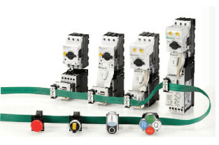
Eaton Industrial Switchgear
FAZ-D2/1-RT
Miniature circuit-breaker
Trade Price
£69.99
Per
1
Unit
EACH
Pack Quantity
1


Information
Eaton Moeller series xEffect - FAZ-NA, FAZ-RT MCB. FAZ-RT, 1-pole, tripping characteristic: D, rated current In: 2 A
Technical Specifications
Product Length/Depth
105 mm
Product Height
75.5 mm
Product Width
17.7 mm
Product Weight
0.125 kg
Compliances
RoHS conform
Certifications
IEC 60947-2
UL 489, CSA C22.2 No. 5
CSA (File No. 204453)
CSA-C22.2 No. 5-09
North America (UL listed, CSA certified)
UL 489
UL (Category Control Number DIVQ)
CE marking
IEC/EN 60947-2
CSA (Class No. 1432-01)
UL (File No. E235139)
Specially designed for North America, suitable as BCPD
EN45545-2
IEC 61373
Application
Feeder circuits, branch circuits
Switchgear for industrial and advanced commercial applications
xEffect - Switchgear for industrial and advanced commercial applications
Number of poles
Single-pole
Number of poles (total)
1
Number of poles (protected)
1
Tripping characteristic
D
Release characteristic
D
Amperage Rating
2 A
Type
FAZ-RT
Miniature circuit breaker
Voltage type
AC
Voltage rating
277 V AC / 480 V AC
Voltage rating at DC
60 V DC
Voltage rating (IEC/EN 60947-2)
240 V AC / 415 V AC
Voltage rating (UL)
277 V
Rated operational voltage (Ue) - max
240 V
Rated insulation voltage (Ui)
440 V
Rated impulse withstand voltage (Uimp)
4 kV
Frequency rating - min
50 Hz
Frequency rating - max
60 Hz
Rated switching capacity (IEC/EN 60947-2)
15 kA
Rated short-circuit breaking capacity (EN 60898) at 230 V
0 kA
Rated short-circuit breaking capacity (EN 60898) at 400 V
0 kA
Rated short-circuit breaking capacity (IEC 60947-2) at 230 V
15 kA
Rated short-circuit breaking capacity (IEC 60947-2) at 400 V
15 kA
Selectivity class
3
Overvoltage category
III
Pollution degree
2
Lifespan, electrical
20000 operations
Direction of incoming supply
As required
Frame
45 mm
Enclosure width
105 mm
Width in number of modular spacings
1
Built-in depth
70.5 mm
Mounting width per pole
17.7 mm
Mounting width
17.7 mm
Mounting Method
Top-hat rail IEC/EN 60715
Mounting position
As required
Degree of protection
UL/CSA Type: -
IP40 (when fitted)
IP20 (IEC)
IP20
Terminals (top and bottom)
Twin-purpose terminals
Connectable conductor cross section (solid-core) - min
1 mm²
Connectable conductor cross section (solid-core) - max
25 mm²
Connectable conductor cross section (multi-wired) - min
1 mm²
Connectable conductor cross section (multi-wired) - max
25 mm²
Terminal protection
Finger and hand touch safe, DGUV VS3, EN 50274
Tightening torque
UL: 4 Nm (36 lb-in) for AWG 6
Max. 2.4 Nm
UL: 2.8 Nm (25 lb-in) for AWG 10 - AWG 8
UL: 2.4 Nm (21 lb-in) for AWG 18 - AWG 12
Rated operational current for specified heat dissipation (In)
2 A
Heat dissipation per pole, current-dependent
0 W
Equipment heat dissipation, current-dependent
1 W
Static heat dissipation, non-current-dependent
0 W
Heat dissipation capacity
0 W
Ambient operating temperature - min
-25 °C
Ambient operating temperature - max
75 °C
10.2.2 Corrosion resistance
Meets the product standard's requirements.
10.2.3.1 Verification of thermal stability of enclosures
Meets the product standard's requirements.
10.2.3.2 Verification of resistance of insulating materials to normal heat
Meets the product standard's requirements.
10.2.3.3 Resist. of insul. mat. to abnormal heat/fire by internal elect. effects
Meets the product standard's requirements.
10.2.4 Resistance to ultra-violet (UV) radiation
Meets the product standard's requirements.
10.2.5 Lifting
Does not apply, since the entire switchgear needs to be evaluated.
10.2.6 Mechanical impact
Does not apply, since the entire switchgear needs to be evaluated.
10.2.7 Inscriptions
Meets the product standard's requirements.
10.3 Degree of protection of assemblies
Does not apply, since the entire switchgear needs to be evaluated.
10.4 Clearances and creepage distances
Meets the product standard's requirements.
10.5 Protection against electric shock
Does not apply, since the entire switchgear needs to be evaluated.
10.6 Incorporation of switching devices and components
Does not apply, since the entire switchgear needs to be evaluated.
10.7 Internal electrical circuits and connections
Is the panel builder's responsibility.
10.8 Connections for external conductors
Is the panel builder's responsibility.
10.9.2 Power-frequency electric strength
Is the panel builder's responsibility.
10.9.3 Impulse withstand voltage
Is the panel builder's responsibility.
10.9.4 Testing of enclosures made of insulating material
Is the panel builder's responsibility.
10.10 Temperature rise
The panel builder is responsible for the temperature rise calculation. Eaton will provide heat dissipation data for the devices.
10.11 Short-circuit rating
Is the panel builder's responsibility. The specifications for the switchgear must be observed.
10.12 Electromagnetic compatibility
Is the panel builder's responsibility. The specifications for the switchgear must be observed.
10.13 Mechanical function
The device meets the requirements, provided the information in the instruction leaflet (IL) is observed.
Current limiting class
3
Features
Additional equipment possible
Functions
Current limiting circuit breaker
Special features
Ambient temperature hint: a 1 °C increase results in a 0.5% linear reduction of current carrying capacity
Used with
Miniature circuit breaker
FAZ-RT
Document Links
Datasheet

