
NZMN3-4-A320/200-SVE
Circ.br. 4p sys/cab. prot.+plug-in cont.
Trade Price
£1,975.69
Per
1
Unit
EACH
Pack Quantity
1

Information
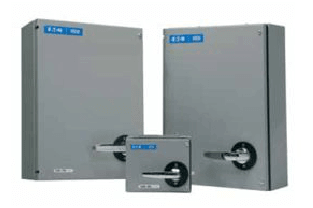
Eaton Moeller series NZM - Molded Case Circuit Breaker. Circuit-breaker, 4p, 320A, 200A in 4th pole, plug-in module, N, 3, 20
Technical Specifications
Product Length/Depth
335 mm
Product Height
215.2 mm
Product Width
185 mm
Product Weight
8.81 kg
Compliances
RoHS conform
10.11 Short-circuit rating
Is the panel builder's responsibility. The specifications for the switchgear must be observed.
10.4 Clearances and creepage distances
Meets the product standard's requirements.
10.12 Electromagnetic compatibility
Is the panel builder's responsibility. The specifications for the switchgear must be observed.
Mounting Method
Built-in device plug-in technique
Amperage Rating
320 A
10.2.5 Lifting
Does not apply, since the entire switchgear needs to be evaluated.
Terminal capacity (copper strip)
Min. 6 segments of 16 mm x 0.8 mm at rear-side connection (punched)
10 segments of 50 mm x 1 mm (2x) at rear-side width extension
Max. 10 segments of 32 mm x 1 mm + 5 segments of 32 mm x 1 mm at rear-side connection (punched)
Handle type
Rocker lever
10.2.3.1 Verification of thermal stability of enclosures
Meets the product standard's requirements.
Ambient storage temperature - min
40 °C
Terminal capacity (copper busbar)
Max. 30 mm x 10 mm + 30 mm x 5 mm direct at switch rear-side connection
10.8 Connections for external conductors
Is the panel builder's responsibility.
Special features
Rated current = rated uninterrupted current: 320 A
Ambient operating temperature - max
70 °C
Position of connection for main current circuit
Front side
Current rating of neutral conductor
60% of phase conductor
Features
Protection unit
Motor drive optional
Electrical connection type of main circuit
Screw connection
Rated short-circuit breaking capacity Ics (IEC/EN 60947) at 400/415 V, 50/60 Hz
50 kA
10.9.3 Impulse withstand voltage
Is the panel builder's responsibility.
Number of poles
Four-pole
Ambient operating temperature - min
-25 °C
10.6 Incorporation of switching devices and components
Does not apply, since the entire switchgear needs to be evaluated.
Overload current setting (Ir)
160 A - 200 A
10.5 Protection against electric shock
Does not apply, since the entire switchgear needs to be evaluated.
Equipment heat dissipation, current-dependent
94 W
Instantaneous current setting (Ii) - min
1920 A
10.13 Mechanical function
The device meets the requirements, provided the information in the instruction leaflet (IL) is observed.
10.2.6 Mechanical impact
Does not apply, since the entire switchgear needs to be evaluated.
10.9.4 Testing of enclosures made of insulating material
Is the panel builder's responsibility.
Application
Use in unearthed supply systems at 690 V
10.3 Degree of protection of assemblies
Does not apply, since the entire switchgear needs to be evaluated.
Rated short-circuit making capacity Icm at 240 V, 50/60 Hz
330 kA
Instantaneous current setting (Ii) - max
19200 A
Overload current setting (Ir) - min
250 A
Short delay current setting (Isd) - min
0 A
Number of auxiliary contacts (normally closed contacts)
0
10.2.3.2 Verification of resistance of insulating materials to normal heat
Meets the product standard's requirements.
10.2.3.3 Resist. of insul. mat. to abnormal heat/fire by internal elect. effects
Meets the product standard's requirements.
Overload current setting (Ir) - max
320 A
Voltage rating
690 V - 690 V
10.9.2 Power-frequency electric strength
Is the panel builder's responsibility.
Short-circuit release non-delayed setting - min
1920 A
Degree of protection
IP20
Short delay current setting (Isd) - max
0 A
Number of auxiliary contacts (change-over contacts)
0
Accessories required
NZM3-XSVS
Ambient storage temperature - max
70 °C
Optional terminals
Box terminal. Connection on rear. Tunnel terminal
10.7 Internal electrical circuits and connections
Is the panel builder's responsibility.
10.10 Temperature rise
The panel builder is responsible for the temperature rise calculation. Eaton will provide heat dissipation data for the devices.
Short-circuit release non-delayed setting - max
3200 A
Rated short-circuit breaking capacity Ics (IEC/EN 60947) at 500 V DC
30 kA
10.2.2 Corrosion resistance
Meets the product standard's requirements.
10.2.4 Resistance to ultra-violet (UV) radiation
Meets the product standard's requirements.
10.2.7 Inscriptions
Meets the product standard's requirements.
Number of auxiliary contacts (normally open contacts)
0
Rated short-circuit breaking capacity Ics (IEC/EN 60947) at 750 V DC
30 kA
Document Links
Datasheet