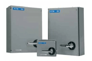
Eaton Commercial, Industrial & Automation
NZMN3-4-AE630/400-T-AVE
C.-breaker 4p syst/line protect + drawer
Trade Price
£3,851.23
Per
1
Unit
EACH
Pack Quantity
1

Information
Eaton Moeller series NZM - Molded Case Circuit Breaker. Circuit-breaker, 4p, 630A, 400A in 4th pole, withdrawable unit, N3-4-AE630/400-T-AVE
Technical Specifications
Product Length/Depth
346 mm
Product Height
260 mm
Product Width
230 mm
Product Weight
14.719 kg
Compliances
RoHS conform
Certifications
IEC/EN 60947
IEC
Application
Use in unearthed supply systems at 690 V
Type
Circuit breaker
Circuit breaker frame type
NZM3
Accessories required
NZM3-4-XAVS
Number of poles
Four-pole
Release system
Electronic release
Features
Protection unit
Motor drive optional
Special features
Maximum back-up fuse, if the expected short-circuit currents at the installation location exceed the switching capacity of the circuit breaker (Rated short-circuit breaking capacity Icn)
Rated current = rated uninterrupted current: 630 A
Reduced neutral conductor protection
Set value in neutral conductor is synchronous with set value Ir of main pole.
R.m.s. value measurement and “thermal memory”
Earth-fault release: Not dependent on mains and control voltages
Ig = 0.35 - 0.4 - 0.5 - 0.6 - 0.7 - 0.8 - 0.9 - 1.0 x In
tg = 0 - 20 - 60 - 100 - 200 - 300 - 500 - 750 - 1000 ms
Terminal capacity hint: Up to 240 mm² can be connected depending on the cable manufacturer.
Current rating of neutral conductor
400 A
60% of phase conductor
Rated short-time withstand current (t = 0.3 s)
3.3 kA
Rated short-time withstand current (t = 1 s)
3.3 kA
Amperage Rating
630 A
Instantaneous current setting (Ii) - min
1260 A
Instantaneous current setting (Ii) - max
5040 A
Overload current setting (Ir)
200 A - 400 A
Overload current setting (Ir) - min
315 A
Overload current setting (Ir) - max
630 A
Short delay current setting (Isd) - min
0 A
Short delay current setting (Isd) - max
0 A
Short-circuit release non-delayed setting - min
1260 A
Short-circuit release non-delayed setting - max
5040 A
Rated short-circuit breaking capacity Ics (IEC/EN 60947) at 230 V, 50/60 Hz
85 kA
Rated short-circuit breaking capacity Ics (IEC/EN 60947) at 400/415 V, 50/60 Hz
50 kA
Rated short-circuit breaking capacity Ics (IEC/EN 60947) at 440 V, 50/60 Hz
35 kA
Rated short-circuit breaking capacity Ics (IEC/EN 60947) at 525 V, 50/60 Hz
13 kA
Rated short-circuit breaking capacity Ics (IEC/EN 60947) at 690 V, 50/60 Hz
5 kA
Rated short-circuit making capacity Icm at 240 V, 50/60 Hz
187 kA
Rated short-circuit making capacity Icm at 400/415 V, 50/60 Hz
105 kA
Rated short-circuit making capacity Icm at 440 V, 50/60 Hz
74 kA
Rated short-circuit making capacity Icm at 525 V, 50/60 Hz
53 kA
Rated short-circuit making capacity Icm at 690 V, 50/60 Hz
40 kA
Short-circuit total breaktime
< 10 ms
Electrical connection type of main circuit
Screw connection
Isolation
300 V AC (between the auxiliary contacts)
500 V AC (between auxiliary contacts and main contacts)
Number of operations per hour - max
60
Handle type
Rocker lever
Utilization category
A (IEC/EN 60947-2)
Overvoltage category
III
Pollution degree
3
Lifespan, electrical
2000 operations at 400 V AC-3
2000 operations at 690 V AC-3
3000 operations at 690 V AC-1
5000 operations at 400 V AC-1
2000 operations at 415 V AC-3
5000 operations at 415 V AC-1
Direction of incoming supply
As required
Voltage rating
690 V - 690 V
Rated impulse withstand voltage (Uimp) at auxiliary contacts
6000 V
Rated impulse withstand voltage (Uimp) at main contacts
8000 V
Mounting Method
Withdrawable
Built-in device slide-in technique (withdrawable)
Degree of protection
IP20
IP20 (basic degree of protection, in the operating controls area)
Degree of protection (IP), front side
IP40 (with insulating surround)
IP66 (with door coupling rotary handle)
Degree of protection (terminations)
IP00 (terminations, phase isolator and strip terminal)
IP10 (tunnel terminal)
Protection against direct contact
Finger and back-of-hand proof to DIN EN 50274/VDE 0106 part 110
Shock resistance
20 g (half-sinusoidal shock 20 ms)
Number of auxiliary contacts (change-over contacts)
0
Number of auxiliary contacts (normally closed contacts)
0
Number of auxiliary contacts (normally open contacts)
0
Position of connection for main current circuit
Front side
Climatic proofing
Damp heat, constant, to IEC 60068-2-78
Damp heat, cyclic, to IEC 60068-2-30
Lifespan, mechanical
15000 operations
Document Links
Datasheet

