
DILM250/22(RA250)
Contactor, 3-p+2N/O 2N/C, 132kW
Trade Price
£1,409.18
Per
1
Unit
EACH
Pack Quantity
1
_3.jpg?twic=v1/max=200x200)
_2.jpg?twic=v1/max=200x200)
_1.jpg?twic=v1/max=200x200)
Information
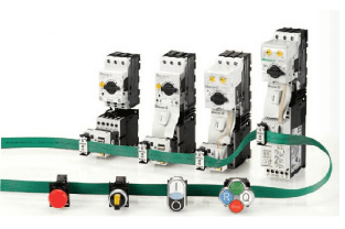
Eaton Moeller® series DILM Contactor, 380 V 400 V 132 kW, 2 N/O, 2 NC, RA 250: 110 - 250 V 40 - 60 Hz/110 - 350 V DC, AC and DC operation, Screw connection DILM250/22(RA250)
Technical Specifications
Product Length/Depth
208 mm
Product Height
189 mm
Product Width
140 mm
Product Weight
7.065 kg
Certifications
VDE 0660
UL 60947-4-1
IEC/EN 60947-4-1
UL File No.: E29096
UL Category Control No.: NLDX
CSA Class No.: 3211-04
UL/CSA
CSA File No. 1017510
North America (UL listed, CSA certified)
EN 45545: Fire protection on railway vehicles
IEC 61373: Vibration and shock, tested for category 1 class B
CE marking
Catalog Notes
Contacts according to EN 50012
Also tested according to AC-3e up to 500 V.
Also suitable for motors with efficiency class IE3.
EN 45545 - Fire protection on railway vehicles: Fire protection class of all plastics according to UL94: V-0 / plastic weight in total: 1.872 kg
Accessories
Fitting options auxiliary contacts: on the side: 2 x DILM820-XHI11(V)-SI; 2 x DILM820-XHI11-SA
Application
Contactors for Motors
Connection
Screw terminals
Degree of protection
IP00
Electromagnetic compatibility
Designed for operation in industrial environments. Its use in residential environments may cause radio-frequency interference, requiring additional noise suppression.
Fitted with:
Suppressor circuit in actuating electronics
Lifespan, electrical
100,000 Operations (at Condensor operation)
Lifespan, mechanical
10,000,000 Operations (AC operated)
10,000,000 Operations (DC operated)
Operating frequency
200 Operations/h
3000 mechanical Operations/h (AC operated)
3000 mechanical Operations/h (DC operated)
Overvoltage category
III
Pollution degree
3
Product category
Contactors
Protection
Finger and back-of-hand proof with terminal shroud or terminal block, Protection against direct contact when actuated from front (EN 50274)
Rated impulse withstand voltage (Uimp)
8000 V AC
Resistance
500 mΩ (Admissible transitional contact resistance - of the external control circuit device when actuating A11)
Shock resistance
8 g, N/C auxiliary contact, Mechanical, according to IEC/EN 60068-2-27, Half-sinusoidal shock 10 ms
10 g, N/O auxiliary contact, Mechanical, according to IEC/EN 60068-2-27, Half-sinusoidal shock 10 ms
10 g, N/O main contact, Mechanical, according to IEC/EN 60068-2-27, Half-sinusoidal shock 10 ms
Signal level
5 V - 15 V, PLC signal level (A3 - A4) to IEC/EN 61131-2 (type 2), Magnet systems
Utilization category
AC-4: Normal AC induction motors: starting, plugging, reversing, inching
AC-3: Normal AC induction motors: starting, switch off during running
AC-1: Non-inductive or slightly inductive loads, resistance furnaces
Ambient operating temperature - min
-40 °C
Ambient operating temperature - max
60 °C
Ambient operating temperature (enclosed) - min
-40 °C
Ambient operating temperature (enclosed) - max
40 °C
Ambient storage temperature - min
-40 °C
Ambient storage temperature - max
80 °C
Climatic proofing
Damp heat, constant, to IEC 60068-2-78
Damp heat, cyclic, to IEC 60068-2-30
Terminal capacity (busbar)
25 mm width, Main connection
Terminal capacity (copper band)
Fixing with flat cable terminal or cable terminal blocks; See terminal capacity for cable terminal blocks
Terminal capacity (flexible with cable lug)
50 - 240 mm²
Terminal capacity (flexible with ferrule)
1 x (0.75 - 2.5) mm², Control circuit cables
2 x (0.75 - 2.5) mm², Control circuit cables
Terminal capacity (solid)
2 x (0.75 - 2.5) mm², Control circuit cables
1 x (0.75 - 2.5) mm², Control circuit cables
Terminal capacity (solid/stranded AWG)
2/0 - 500 MCM, Main cables
18 - 14, Control circuit cables
Terminal capacity (stranded with cable lug)
70 - 240 mm²
Width across flats
16 mm
Screw size
M3.5, Terminal screw, Control circuit cables
M10, Terminal screw, Main connections
Screwdriver size
2, Terminal screw, Control circuit cables, Pozidriv screwdriver
Tightening torque
1.2 Nm, Screw terminals, Control circuit cables
24 Nm, Main cable connection screw/bolt
Inrush current
Max. 30 x Ie (peak)
Rated breaking capacity at 220/230 V
2500 A
Rated breaking capacity at 380/400 V
2500 A
Rated breaking capacity at 500 V
2500 A
Rated breaking capacity at 660/690 V
2500 A
Rated breaking capacity at 1000 V
760 A
Rated insulation voltage (Ui)
1000 V
Rated making capacity (cos phi to IEC/EN 60947)
3000 A
Rated operational current (Ie)
133 A at 690 V (Individual compensation, three-phase capacitors, open)
220 A at up to 525 V (Individual compensation, three-phase capacitors, open)
Rated operational current (Ie) at AC-1, 380 V, 400 V, 415 V
429 A
Rated operational current (Ie) at AC-3, 220 V, 230 V, 240 V
250 A
Rated operational current (Ie) at AC-3, 380 V, 400 V, 415 V
250 A
Rated operational current (Ie) at AC-3, 440 V
250 A
Rated operational current (Ie) at AC-3, 500 V
250 A
Rated operational current (Ie) at AC-3, 660 V, 690 V
185 A
Rated operational current (Ie) at AC-3, 1000 V
76 A
Rated operational current (Ie) at AC-4, 220 V, 230 V, 240 V
200 A
Rated operational current (Ie) at AC-4, 440 V
200 A
Rated operational current (Ie) at AC-4, 500 V
200 A
Rated operational current (Ie) at AC-4, 660 V, 690 V
150 A
Rated operational current (Ie) at AC-4, 1000 V
76 A
Rated operational power at AC-3, 240 V, 50 Hz
85 kW
Rated operational power at AC-3, 380/400 V, 50 Hz
132 kW
Rated operational power at AC-3, 415 V, 50 Hz
143 kW
Rated operational power at AC-3, 1000 V, 50 Hz
108 kW
Rated operational power at AC-4, 220/230 V, 50 Hz
62 kW
Rated operational power at AC-4, 240 V, 50 Hz
68 kW
Rated operational power at AC-4, 415 V, 50 Hz
117 kW
Rated operational power at AC-4, 440 V, 50 Hz
125 kW
Rated operational power at AC-4, 500 V, 50 Hz
138 kW
Rated operational power at AC-4, 660/690 V, 50 Hz
137 kW
Rated operational voltage (Ue) at AC - max
1000 V
Rated operational power at AC-4, 1000 V, 50 Hz
108 kW
Safe isolation
500 V AC, Between the contacts, According to EN 61140
500 V AC, Between coil and contacts, According to EN 61140
Special purpose rating of definite purpose rating
1800 A, LRA 600 V 60 Hz 3-ph, 100,000 cycles acc. to UL 1995, (UL/CSA)
250 A, FLA 600 V 60 Hz 3-ph, 100,000 cycles acc. to UL 1995, (UL/CSA)
300 A, FLA 480 V 60 Hz 3-ph, 100,000 cycles acc. to UL 1995, (UL/CSA)
2050 A, LRA 480 V 60 Hz 3-ph, 100,000 cycles acc. to UL 1995, (UL/CSA)
Short-circuit current rating (basic rating)
700 A, max. Fuse, SCCR (UL/CSA)
600 A, max. CB, SCCR (UL/CSA)
18 kA, SCCR (UL/CSA)
Short-circuit current rating (high fault at 480 V)
250 A, max. CB, SCCR (UL/CSA)
18 kA, Fuse, SCCR (UL/CSA)
65 kA, CB, SCCR (UL/CSA)
700 A, Class L, max. Fuse, SCCR (UL/CSA)
Short-circuit current rating (high fault at 600 V)
18 kA, Fuse, SCCR (UL/CSA)
700 A, Class J, max. Fuse, SCCR (UL/CSA)
600 A, max. CB, SCCR (UL/CSA)
18 kA, CB, SCCR (UL/CSA)
Short-circuit protection rating (type 1 coordination) at 1000 V
200 A gG/gL
Short-circuit protection rating (type 1 coordination) at 400 V
400 A gG/gL
Short-circuit protection rating (type 1 coordination) at 690 V
400 A gG/gL
Short-circuit protection rating (type 2 coordination) at 1000 V
160 A gG/gL
Short-circuit protection rating (type 2 coordination) at 400 V
315 A gG/gL
Short-circuit protection rating (type 2 coordination) at 690 V
315 A gG/gL
Conventional thermal current ith (1-pole, enclosed)
750 A
Conventional thermal current ith (3-pole, enclosed)
300 A
Conventional thermal current ith at 55°C (3-pole, open)
365 A
Conventional thermal current ith of main contacts (1-pole, open)
875 A
Switching capacity (main contacts, general use)
350 A, Maximum motor rating (UL/CSA)
Switching capacity (auxiliary contacts, general use)
15 A, 600 V AC, (UL/CSA)
1 A, 250 V DC, (UL/CSA)
Switching capacity (auxiliary contacts, pilot duty)
A600, AC operated (UL/CSA)
P300, DC operated (UL/CSA)
Behavior in marginal and transitional conditions
Sealing - Voltage interruptions (0 - 0.2 x Uc min <= 10 ms: Time is bridged successfully
Sealing - Pick-up phase (0 - 0.7 x Uc min: Contactor does not switch on
Sealing - Voltage drops (0.2 - 0.6 x Uc min) > 12 ms: Drop-out of the contactor
Sealing - Pick-up phase (0.7 x Uc min - 1.15 x Uc max): Contactor switches on with certainty
Sealing - Voltage drops (0.2 - 0.6 x Uc min <=12 ms: Time is bridged successfully
Sealing - Voltage interruptions 0 - 0.2 x Uc min) > 10 ms: Drop-out of the contactor
Sealing - Excess voltage (1.15 - 1.3 x Uc max): Contactor remains switched on
Sealing - Voltage drops (0.6 - 0.7 x Uc min: Contactor remains switched on
Drop-out voltage
AC operated: 0.2 x US max - 0.6 x US min, AC operated
0.2 x US max - 0.6 x US min, DC operated
Duty factor
100 %
Pick-up voltage
0.7 - 1.15 V AC x Us
0.7 - 1.15 V DC x Us
Power consumption
Control transformer with uk <= 6%
Power consumption, pick-up, 50 Hz
250 W, Pull-in power, Coil in a cold state and 1.0 x Us
380 VA, Pull-in power, Coil in a cold state and 1.0 x Us
Power consumption, pick-up, 60 Hz
380 VA, Pull-in power, Coil in a cold state and 1.0 x Us
250 W, Pull-in power, Coil in a cold state and 1.0 x Us
Power consumption, sealing, 50 Hz
10.5 VA, Coil in a cold state and 1.0 x Us
0 CO, Coil in a cold state and 1.0 x Us
5.5 W, Coil in a cold state and 1.0 x Us
Power consumption, sealing, 60 Hz
5.5 W, Coil in a cold state and 1.0 x Us
10.5 VA, Coil in a cold state and 1.0 x Us
Rated control supply voltage (Us) at AC, 50 Hz - min
110 V
Rated control supply voltage (Us) at AC, 50 Hz - max
250 V
Rated control supply voltage (Us) at AC, 60 Hz - min
110 V
Rated control supply voltage (Us) at AC, 60 Hz - max
250 V
Rated control supply voltage (Us) at DC - min
110 V
Rated control supply voltage (Us) at DC - max
250 V
Switching time (AC operated, make contacts, closing delay) - max
100 ms
Switching time (AC operated, make contacts, opening delay) - max
110 ms
Assigned motor power at 200/208 V, 60 Hz, 3-phase
75 HP
Assigned motor power at 230/240 V, 60 Hz, 3-phase
100 HP
Assigned motor power at 460/480 V, 60 Hz, 3-phase
200 HP
Assigned motor power at 575/600 V, 60 Hz, 3-phase
250 HP
Number of auxiliary contacts (normally closed contacts)
2
Number of auxiliary contacts (normally open contacts)
2
Number of contacts (normally closed contacts)
2
Number of contacts (normally open contacts)
2
Equipment heat dissipation, current-dependent Pvid
28 W
Heat dissipation capacity Pdiss
0 W
Heat dissipation per pole, current-dependent Pvid
9.33 W
Rated operational current for specified heat dissipation (In)
250 A
Static heat dissipation, non-current-dependent Pvs
5.5 W
10.2.2 Corrosion resistance
Meets the product standard's requirements.
10.2.3.1 Verification of thermal stability of enclosures
Meets the product standard's requirements.
10.2.3.2 Verification of resistance of insulating materials to normal heat
Meets the product standard's requirements.
10.2.3.3 Resist. of insul. mat. to abnormal heat/fire by internal elect. effects
Meets the product standard's requirements.
10.2.4 Resistance to ultra-violet (UV) radiation
Meets the product standard's requirements.
10.2.5 Lifting
Does not apply, since the entire switchgear needs to be evaluated.
10.2.6 Mechanical impact
Does not apply, since the entire switchgear needs to be evaluated.
10.2.7 Inscriptions
Meets the product standard's requirements.
10.3 Degree of protection of assemblies
Does not apply, since the entire switchgear needs to be evaluated.
10.4 Clearances and creepage distances
Meets the product standard's requirements.
10.5 Protection against electric shock
Does not apply, since the entire switchgear needs to be evaluated.
10.6 Incorporation of switching devices and components
Does not apply, since the entire switchgear needs to be evaluated.
10.7 Internal electrical circuits and connections
Is the panel builder's responsibility.
10.8 Connections for external conductors
Is the panel builder's responsibility.
10.9.2 Power-frequency electric strength
Is the panel builder's responsibility.
10.9.3 Impulse withstand voltage
Is the panel builder's responsibility.
10.9.4 Testing of enclosures made of insulating material
Is the panel builder's responsibility.
10.10 Temperature rise
The panel builder is responsible for the temperature rise calculation. Eaton will provide heat dissipation data for the devices.
10.11 Short-circuit rating
Is the panel builder's responsibility. The specifications for the switchgear must be observed.
10.12 Electromagnetic compatibility
Is the panel builder's responsibility. The specifications for the switchgear must be observed.
10.13 Mechanical function
The device meets the requirements, provided the information in the instruction leaflet (IL) is observed.
Document Links
Datasheet